Hi Roman,
so cool that you are pushing through the ROS2 Nav2 project! That is the way to go, since, by doing the project you will encounter a lot of other problems that do not appear in the controlled environment of the course.
Like for example, this one about the map!
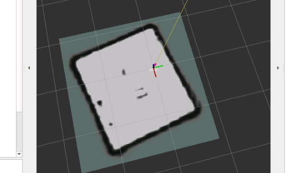
Definitely, there is something wrong in your map. First of all, the walls doesn’t look straight. That could be because your parameters on the cartographer lua file are not correct, so you do not detect the walls until you are very close to them (that is not correct because the range of the Turtlebot3 lidar can detect the whole environment from any position of that environment).
Another possible reason is that you are providing to the robot a very high speed, then, there is a large space between each laser lecture, so the odometry condition for the SLAM algorithm is not maintained.
Second, you are not showing the obstacles in the middle. That also makes me suspect you don’t have the proper values in the parameters:
TRAJECTORY_BUILDER_2D.max_rang
I know the simulation goes slow, that is what we have now. Take into account that you are launching:
the simulation
the bridge
the rviz
the slam algorithm
the keyboard teleop
That’s a lot!
Please check the video of this link to see how it works on my case. I just did this example with a proper configuration file. You can see my real time factor is 0.35, even worst than yours. But that is not important for what we are doing here in the project. The speed at which the simulation runs is not important as long as you do not stress the speed of the robot. Try not to provide linear speed larger than 0.05m/s and angular velocities larger than 0.2 rad/s
About the particles plugin, let us install it and come back when done.
yes i encounter a lot of problems through the courses. Most times they are easy to solve.
But for the actual problem i’m happy to have experienced support.
I already set the max_range parameter to 3.5.
Altough i used an extrem low speed my map isn’t as fine as yours.
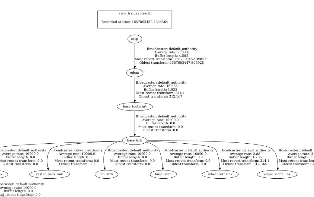
One thing i noticed is that the robot tf-frames are outside of nowhere.
The Odom<-Map transformation is corrupt.
The only two strange things that I see in your LUA config file are:
the parameter tracking_frame should be the frame of the center of the robot, that usually is base_footprint or base_link. You set it to imu_link. Even if that may work, it is not a good idea to set that when you are not using an IMU for the mapping (which is the case here). So change this to base_footprint.
You set to false the TRAJECTORY_BUILDER_2D.use_online_correlative_scan_matchingparameter. That is an important parameter because it indicates if we have to use a scan matching or not. Scan matching helps the algorithm determine the amount of movement done by the robot, so it can check if the odometry is good or not. If you disconnect it (set to false) then you are putting it more difficult to the mapper. Please set it to true.
Try again with those two modifications and let’s see.
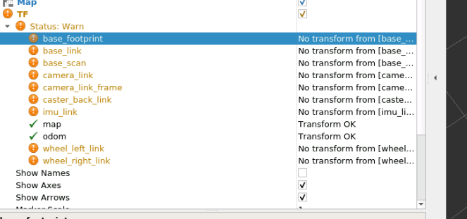
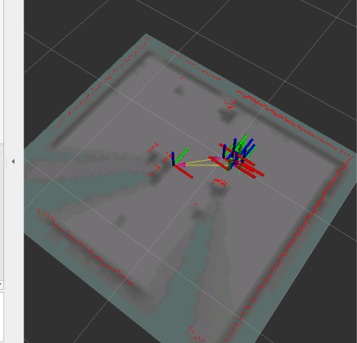
About the frame, what you are showing me is the TF-tree of your robot, which looks correct. I meant, display the TF frames in Rviz. You are already doing that (because I can see the map frame in your rviz picture, but I cannot see the odom. That is why I wanted you to show me where it is in rviz (it is at the end of the yellow arrow. That arrow indicates the connection between the map frame and the odom frame.
Also there is something strange because the base_footprint doesn’t appear in rviz.
Something is wrong here: Have you seen the video I put on my first answer in this thread? There you can see that I am in mapping phase. During mapping phase, you should be able to see the robot creating the map. You should see the laser, the robot and the map being created. Please, do that and send me a picture of the robot doing the map (not when completely done, but when in the process of doing it).
During that state, you should not see the Warning in the TF display. Everything must be transform ok. If it is not, then there is a problem with the simulation, something is broken. In that case, kill the mapping, and then restart the simulation (with the restart button of the right).
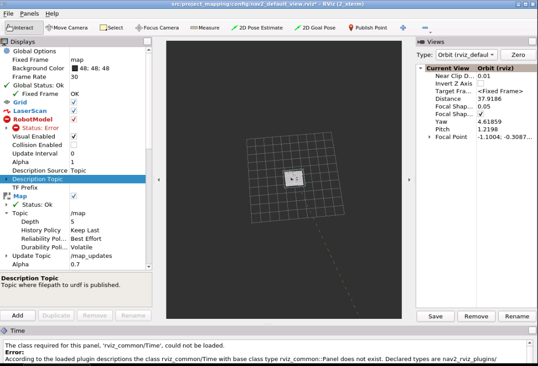
PLEASE, PLEASE, PLEASE, very important: when taking screenshots, take them of the full screen, not only of the small window with the image, because you are leaving a lot of information of what is happening out, so it is more difficult to understand your problem.
I changed the tracking_frame to base_footprint and also the TRAJECTORY_BUILDER_2D.use_online_correlative_scan_matching to true.
As a result the map quality is much better. Thank you.
Sorry i can’t visualize it in a proper way because the odom frame is so much away from the map frame that it gets unvisible when i scroll out.
