Hi
I noticed that the formula used in the calculation py file is the situation if the origin at the center of mass, or the geometry center. But I guess the convention to set a link origin is at the tip where connects with the joint but not the CoM. Will this cause any problem?
Thanks!
Hi,
Not at all. You can specify in Gazebo to use a different pose for the inertia (CoM) from the visual and collision elements.
  <inertial>
    <!-- NOTE:reflect==-1 for right side, reflect==1 for the left side -->
    <mass value="6.01769" />
    <origin xyz="${0.5*((reflect+1)*ual_xyz1+(1-reflect)*uar_xyz1)} ${0.5*((reflect+1)*ual_xyz2+(1-reflect)*uar_xyz2)} ${0.5*((reflect+1)*ual_xyz3+(1-reflect)*uar_xyz3)}" />
    <inertia  ixx="${0.5*((reflect+1)*ual_ixx+(1-reflect)*uar_ixx)}"
              ixy="${0.5*((reflect+1)*ual_ixy+(1-reflect)*uar_ixy)}"
              ixz="${0.5*((reflect+1)*ual_ixz+(1-reflect)*uar_ixz)}"
              iyy="${0.5*((reflect+1)*ual_iyy+(1-reflect)*uar_iyy)}"
              iyz="${0.5*((reflect+1)*ual_iyz+(1-reflect)*uar_iyz)}"
              izz="${0.5*((reflect+1)*ual_izz+(1-reflect)*uar_izz)}" />
  </inertial>

  <visual>
    <origin xyz="0 0 0" rpy="0 0 0" />
    <geometry>
      <mesh filename="package://pr2_description/meshes/upper_arm_v0/upper_arm.dae"  />
    </geometry>

    <material name="Green" />
  </visual>

  <collision>
    <origin xyz="0 0 0" rpy="0 0 0" />
    <geometry>
      <mesh filename="package://pr2_description/meshes/upper_arm_v0/upper_arm.stl"  />
    </geometry>
  </collision>

</link>
Here you see that the inertial and the visual/collision have different origins ;).
Have a look ath these examples of URDF and you will see a lot of examples concerning this matter: http://wiki.ros.org/urdf/Examples
Thanks for your reply, but I’m still a bit confused about the origins of inertia, visual, and collision.
Using the first case in the Building the Visual Robot with URDF chapter and the tutorial here: Inertial/Visual/Collision origin is the reference frame of the element with respect to the reference frame of the link.
-
The origin of the base_link origin is w.r.t the world frame and the origin of the roll_M1_link is defined w.r.t the joint(child) frame. Am I correct?
-
When I need to import a 3D cad model into the gazebo world, there is one step to set the origin of the model. Definition of it is “the location of this point determines where the object is located in 3D space”, and there is another parameter Transform in blender need to be set, I checked in the Rviz that the TF frame will follow the setting of Transform in blender. But I don’t understand why the origin and Transform can be two different points, in my understanding, the origin should be the origin of the Transform in blender. Besides, Is the Transform in belnder also the reference frame of the link?
-
I assume the inertia parameter will be used for calculating the controller torque and you said that the origin of inertia can be different from the origins of visual and collision. Does that mean we always set the inertia origin at the CoM no matter how the visual origin is defined and the ROS will figure out the actual inertia with the TF frame itself? Or the inertia origin relates to the visual origin?
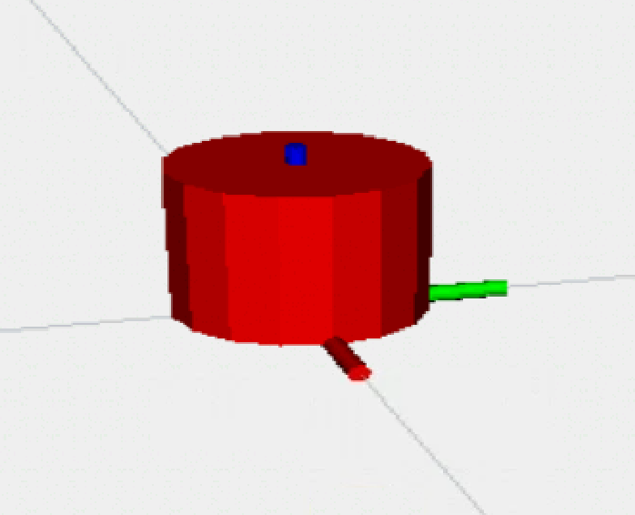
In this case, the visual origin is modified so the TF frame is at the bottom of the cylinder, and if we want to use the given formula in that py file, we have to set the inertia origin (0, 0, h/2). Otherwise, we have to consider the parallel axis theorem with the default inertia origin (0, 0, 0)